

Content
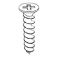
Every failed sheet metal connection traces back to one of three decisions made before the driver ever touches the fastener: the wrong gauge, the wrong drill point, or the wrong thread pitch for the base material. Sheet metal ranges from soft 0.5 mm aluminum cladding to 3 mm cold-rolled steel brackets, and a fastener tuned for one thickness will either spin freely in the other or shear the panel edge on entry. Understanding how self-tapping screws actually cut and form threads inside a hole is the starting point for specifying the right part rather than guessing from a parts bin.
A self-tapping fastener does two jobs at once: it creates a mating thread as it advances, and it clamps the joined layers together once seated. Thread-forming variants displace metal outward without removing material, which works well in thin, ductile sheet where the displaced metal flows into the thread root. Thread-cutting variants shave away material with a slotted or fluted tip, which suits thicker or harder sheet where forming would otherwise crack the panel or generate excessive torque. Mixing up the two categories is the single most common cause of stripped holes reported by fabrication shops.
Displaces material radially. Best for sheet under 1.5 mm and softer alloys where a tight, gas-tight seal matters more than raw pull-out strength.
Removes a curl of material as it advances. Preferred for sheet 1.5 mm and above, or for repeated assembly and disassembly cycles.
Combines a drill tip with a cutting thread in one part, eliminating a separate pilot-hole step on steel up to roughly 3 mm.
Gauge is the diameter code stamped on the packaging, and it should be selected against the thinner of the two layers being joined, not the thicker one. A gauge that is too large for a thin outer skin will deform the surrounding metal into a visible dimple; a gauge that is too small for a thick bracket will thread only a few turns before running out of engagement depth.
Length is calculated differently depending on joint type. For a lap joint through two sheets, the screw should pass fully through both layers plus two to three exposed threads on the back side to confirm full engagement without excess protrusion. For a screw driven into a formed flange or extruded profile, length should leave at least three full threads of standoff below the flange face, since fewer threads reduce pull-out resistance sharply and more threads risk bottoming out against an internal wall.
| Sheet Combination | Typical Gauge | Typical Length |
| 0.6mm to 0.6mm lap joint | No.6 | 9.5mm |
| 1.0mm to 1.6mm bracket | No.8 | 13mm |
| 1.6mm to 2.4mm frame | No.10 | 16mm |
| 2.4mm to 3.0mm structural | No.12 | 19mm |
The tip of a self-drilling screw is classified by a point number that roughly corresponds to the combined thickness of material it can penetrate without a pilot hole. Point 1 and Point 2 tips handle light sheet from 0.7 mm to 3.2 mm combined. Point 3 tips extend that range toward 4.8 mm, and Point 5 tips are built for structural steel sections up to around 6.4 mm. Selecting a tip rated below the actual stack thickness forces the installer to increase driver torque to compensate, which raises the odds of thread stripping or head snap-off rather than solving the underlying mismatch.
Flute count matters as much as point number. A single-lobed drill tip clears swarf efficiently in thin sheet but can wander off-center in thicker stacks; a fluted or winged tip channels debris away from the hole in structural-gauge steel and reduces the axial force needed to start penetration. For repeated production runs, standardizing on one point rating per material band, rather than one rating for the whole job, keeps cycle time and reject rate predictable across shifts.
A drill point one size too small does not simply take longer to penetrate. It generates localized heat that work-hardens the hole edge, which then resists the following thread-forming pass and produces a loose, under-torqued joint even though the driver reported full seating.
Point wear is easy to overlook because it degrades gradually rather than failing all at once. A fresh Point 2 tip might comfortably clear a 3 mm stack, but after several thousand cycles the same tip can start to struggle with 2 mm sheet, and operators often respond by pressing harder rather than swapping the bit. Tracking cycle counts per bit, even with a simple tally sheet at the workstation, catches this drift before it shows up as a spike in rejected joints. Shops running two or three shifts on the same line often find that staggering bit replacement across shifts, rather than waiting for a visible failure, keeps reject rates flatter across the week.
Thread pitch, the distance between adjacent thread crests, governs how much material each thread engages and how fast the screw advances per rotation. Coarse pitch threads have fewer threads per inch and a deeper thread profile, giving strong resistance to stripping in thin, soft sheet where each thread needs to bite hard into limited material. Fine pitch threads pack more threads into the same length, spreading clamp load across more contact points, which suits thicker sheet and applications facing vibration.
The crossover point where fine pitch begins to outperform coarse pitch generally falls between 1.6 mm and 2.0 mm, depending on alloy hardness. Below that band, coarse pitch consistently produces better retained torque because there simply is not enough material depth for fine threads to fully form. Above that band, fine pitch resists thread stripping under repeated load cycles because more threads are sharing the same clamp force, so no single thread carries a disproportionate share of the stress.
Pitch selection also interacts with the pilot hole tolerance chosen upstream. A punched or drilled hole that runs even a few hundredths of a millimeter oversized will let a coarse pitch thread engage almost normally, since the deeper thread profile has more material to grip. A fine pitch thread in the same oversized hole loses a much larger share of its available engagement, because each individual thread is shallower to begin with. This is one reason production drawings for thicker, fine-pitch assemblies typically call out a tighter pilot hole tolerance than drawings written for thin, coarse-pitch sheet.
Two panels of identical thickness can behave completely differently under the same fastener if their alloy composition differs. Aluminum sheet is roughly a third the hardness of mild steel at equivalent thickness, so a drill point rated for steel will punch through aluminum almost too easily, sometimes causing the fastener to wobble before the thread engages. Stainless sheet sits at the opposite end, generating far more frictional heat during drive-in, which is why stainless-compatible fasteners typically carry a harder case treatment on the point and thread flanks.
Ductility also affects how forgiving a joint is to over-driving. Soft aluminum will keep deforming past the point of full seating, meaning a driver set for steel torque will dish the surrounding panel before the clutch trips. Harder alloys resist that deformation, which shifts the risk toward thread stripping instead of dishing once the clutch setting is too aggressive. Matching driver torque and clutch settings to the specific alloy, not just the thickness, closes this gap.
Coating choice on the fastener itself interacts with these material differences too. A zinc-plated carbon steel screw driven into bare aluminum can set up a mild galvanic reaction over time in damp environments, gradually loosening the joint even if the initial mechanical seating was correct. Fasteners with a coating compatible with the base sheet, or a physical barrier such as a nylon washer where dissimilar metals must meet, avoid this slow degradation. It rarely shows up in the first weeks of service, which is exactly why it gets missed during initial quality checks and only surfaces months later as an unexplained batch of loose joints.
Consistency in fastening comes less from the screw itself and more from a repeatable installation sequence. Shops that see the fewest callbacks tend to follow the same checklist regardless of operator experience level.
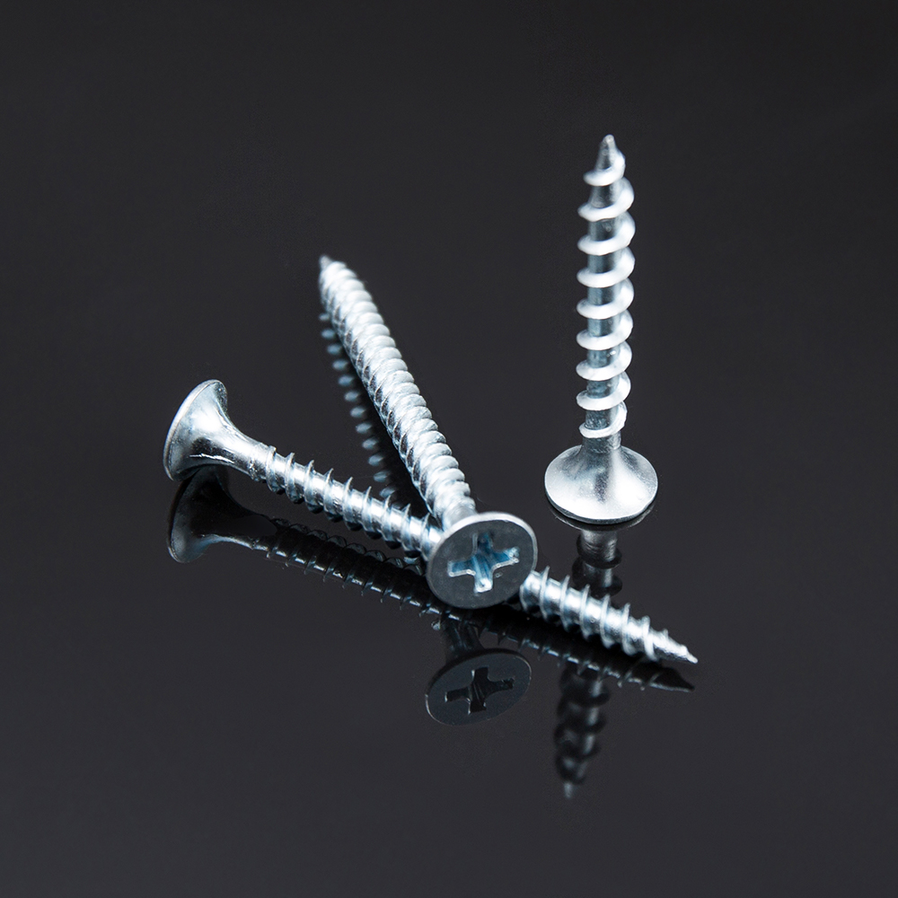 Perpendicular alignment and steady drive speed reduce side-load on the thread during installation.
Pilot holes deserve a separate note. For thread-forming screws in thin sheet, skipping the pilot hole is usually fine and even preferred, since the formed thread relies on undisturbed material around the hole. For thread-cutting screws in thicker sheet, a pilot hole sized roughly 85 percent of the screw's minor diameter reduces drive torque substantially without sacrificing thread engagement, and it noticeably extends bit life on high-volume jobs.
Fixturing plays a quiet but significant role in torque consistency as well. Panels that are allowed to flex during driving absorb part of the applied force as deflection rather than clamp-up, which shows up later as a joint that reads correctly on an initial torque check but loosens after the first few load cycles once the panel settles. Clamping the stack firmly against a rigid backing plate during assembly, even for a few seconds while the driver seats the fastener, removes this variable and makes torque readings far more repeatable from one operator to the next.
Most field failures fall into a short list of recognizable patterns, and each one points back to a specific mismatch rather than a random defect.
| Symptom | Likely Root Cause | Correction |
| Screw spins without biting | Gauge too small or hole oversized | Step up one gauge or reduce pilot hole size |
| Head snaps off during drive | Torque set too high for material hardness | Lower clutch setting, verify on scrap first |
| Panel dimples around head | Gauge too large for thin outer sheet | Step down gauge, add a washer head variant |
| Loose joint after weeks in service | Coarse pitch used on thicker vibrating panel | Switch to fine pitch, recheck torque spec |
| Screw wanders before penetrating | Drill point too aggressive for soft alloy | Select a lower point number, reduce feed pressure |
A useful diagnostic habit is to keep a small set of failed samples from each production run and examine the thread profile under magnification. A stripped hole with clean, undamaged threads on the fastener itself usually points to a hole or gauge mismatch. A fastener with visibly worn or rounded thread crests points instead to excessive drive cycles on a bit that should have been replaced several thousand cycles earlier.
It also helps to separate a true fastener defect from a process defect before changing the specification. Swapping to a heavier gauge or a different pitch to solve what is actually a fixturing or torque calibration problem often introduces a new set of issues, such as increased dimpling, without resolving the original complaint. A short root-cause pass, comparing a handful of failed samples against the installation checklist before touching the bill of materials, usually resolves the issue faster and avoids unnecessary part number changes across a production run that was otherwise performing well.
For shops running the same handful of sheet combinations repeatedly, it is worth documenting a short specification card per assembly rather than re-deriving gauge, length, point, and pitch from scratch each time. A typical card lists the two material layers, their thicknesses, the chosen sheet metal screws gauge and length, drill point rating, pitch type, target driver torque, and any pilot hole requirement. Attaching this card to the work order removes ambiguity between shifts and gives new operators a reference that does not depend on tribal knowledge.
When a new sheet combination appears that is not already documented, a quick three-step trial run works well: drive one sample at the manufacturer baseline torque and inspect for dimpling or stripping, adjust torque by small increments in either direction based on that result, then lock the setting once three consecutive samples seat cleanly with consistent standoff. This trial approach takes a few minutes and prevents an entire batch from being run at an unverified setting.
Fastener choice also interacts with corrosion exposure, though that consideration sits outside pure mechanical fit. Interior brackets rarely need coated self-drilling fasteners, but anything facing weather, washdown, or coastal air benefits from a corrosion-resistant coating or stainless construction even when the base mechanical rating would otherwise call for a standard carbon steel part.
A self-tapping screw cuts or forms its own thread as it advances but still generally needs a pilot hole in metal. A self-drilling screw adds a drill-point tip so it can bore its own starter hole and form the thread in a single pass, which speeds up assembly on thicker sheet.
An under-torqued joint will still resist hand rotation and show intact threads on removal. A stripped hole spins freely with little resistance and often shows a smoothed, rounded hole edge rather than a defined thread profile.
It can, but gauge should be sized to the thinner layer to avoid dimpling, while length should still account for full engagement through the thicker layer. This is why many assemblies use one gauge with a length chosen specifically for the combined stack rather than either sheet alone.
Yes. Coarse pitch threads advance faster per rotation since each turn covers more linear distance, which shortens cycle time on high-volume runs where thin sheet does not require fine pitch performance.
Aluminum deforms at lower force than steel, so a torque setting calibrated for steel will over-drive and dimple aluminum before the clutch trips, while the same setting may under-seat a steel joint. Torque settings should be verified per material, not assumed from a single default.






 English
 Español
 عربى
عربى